
It’s also important to securely mount the batteries and the associated cabling and to properly protect the battery cables. If either cable becomes shorted to the other or to ground, the fuses by the batteries will blow and prevent a fire. It is also critically important for safety reasons to properly fuse the connections between the batteries at both ends and in both the +13.8V and ground leads! We used high current fuses (the insulated holders to the right of the battery in the picture above on both ends of the battery cabling. The batteries must be identical when connected this way to ensure that differences in operating voltage do not result in uneven charging. Both batteries are connected in parallel with custom-made 2 ga cables for both +13.8V and ground. This profile is ideal of supplying a mobile amplifier.
TUNEMATIC ANTENNA TUNER SERIES
The Red-Top series provides very high current for short periods of time (ex engine cranking). We choose an Optima Red-Top series battery for both the secondary battery and as a replacement for our truck’s primary battery.
TUNEMATIC ANTENNA TUNER INSTALL
The easiest way to achieve this in our application was to install a secondary battery in the bed of our truck. The next problem to solve is to provide 100A+ of peak current during transmit without excessive voltage drop (you want to have no more than 0.5V of drop between your primary battery and the power terminals of your amplifier). It’s important that your vehicle’s alternator is capable of supplying enough current to operate the amplifier and the rest of your vehicle’s electrical system with overloading or major drops in voltage. We were fortunate that our F-150 Truck came with a 150A alternator from the factory. I am going to cover each of these points as they were handled in our installation.
TUNEMATIC ANTENNA TUNER FULL
Proper physical mounting and adequate cooling to dissipate the heat generated (a 500W amplifier will generate approximately 500W of heat when operating at full output).Beefing up the vehicle’s electrical system to be able to supply adequate 13.8V power (a 500W mobile amplifier will require 60A – 80A of sustained current when transmitting at full output and may draw close to 100A on peaks).One must pay a great deal of attention to the following areas: As Alan Applegate ( K0BG), author of the excellent website on mobile HF points out, installing an amplifier in a mobile application is not a trivial project. The next step in this phase of our project was the installation of a mobile HF amplifier and some accessories to make the operation of our mobile HF station easier. After properly adjusting both shunt coils, I was able to get a good match (SWR < 1.4:1) across the 160m, 80m and 40m bands. The relay switches in the appropriate shunt coil under the control of a switch that I’ve added to our truck’s console.

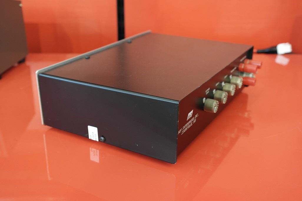
The unit contains two shunt coils (one for 160m and one for 80m/40m) and a 12V relay.


 0 kommentar(er)
